ADC - Analog-to-Digital Conversion
Analog-to-Digital Conversion is yet another nice feature you can get with a PIC. It's basically used to convert a voltage as an analog source (continuous) into a digital number (discrete).
ADC with water...
To better understand ADC, imagine you have some water going out of a pipe, and you'd like to know how many water it goes outside. One approach would be to collect all the water in a bucket, and then measure what you've collected. But what if water flow never ends ? And, more important, what if water flow isn't constant and you want to measure the flow in real-time ?
The answer is ADC. With ADC, you're going to extract samples of water. For instance, you're going to put a little glass for 1 second under the pipe, every ten seconds. Doing the math, you'll be able to know the mean rate of flow.
The faster you'll collect water, the more accurate the rate will be. That is, if you're able to collect 10 glasses of water each second, you'll have a better overview of the rate of water than if you collect 1 glass each ten seconds. This is the process of making a continuous flow a discrete, finite value. And this is about resolution, one important property of ADC (and this is also about clock speed...). The higher the resolution, the more accurate the results.
Now, what if the water flow is so high that your glass gets filled before the end of the sample time ? You could use a bigger glass, but let's assume you can't (scenario need...). This means you can't measure any water flow, this one has to be scaled according to your glass. On the contrary, the water flow may be so low samples you extract may not be relevant related to the glass size (only few drops). Fortunately, you can use a smaller glass (yes, scenario need) to scale down your sample. That is about voltage reference, another important property.
Leaving our glass of water, many PICs provide several ADC channels: pins that can do this process, measuring voltage as input. In order to use this peripheral, you'll first have to configure how many ADC channels you want. Then you'll need to specify the resolution, usually using 8 bits (0 to 255), 10 bits (0 to 1024) or even 12 bits (0 to 4096). Finally, you'll have to setup voltage references depending on the voltage spread you plan to measure.
ADC with jallib...
- Not all PICs have ADC module (...)
- Analog pins are dispatched differently amongst PICs, still for user's sake, they have to be automatically configured as input. We thus need to know, for each PIC, where analog pins are...
- Some PICs have their analog pins dependent from each other, and some are independent (more on this later)
- Clock configuration can be different
- As previously stated, some PICs have 8-bits low resolution ADC module, some have 10-bits high resolution ADC module1
- Some PICs can have two external voltage references (VRef+ and VRef-), only one voltage reference (Vref+ or Vref-) and some can't handle external voltage references at all
- (and probably other differences I can't remember :)...
Luckily most of these differences are transparent to users...
Dependent and independent analog pins
OK, let's write some code ! But before this, you have to understand one very important point: some PICs have their analog pins dependent from each other, some PICs have their analog pins independent from each other. "What is this suppose to mean ?" I can hear...
Let's consider two famous PICs: 16F877 and 16F88. 16F877 datasheet explains how to configure the number of analog pins, and vref, setting PCFG bits:
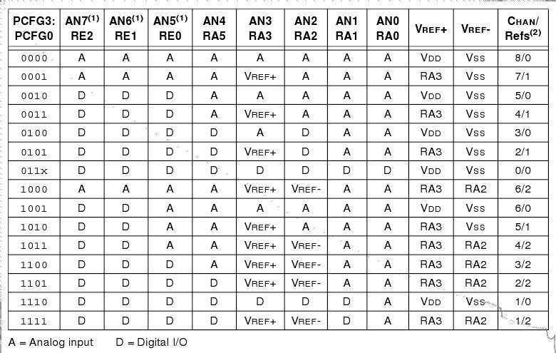
- the number of ADC channels you want,
- and amongst them, the number of Vref channels
Now, let's consider 16F88. In this case, there's no such table:
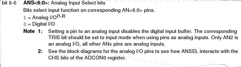
Mmmh... OK, there are ANS bits, one for each analog pins. Setting an ANS bit to 1 sets the corresponding pin to analog. This means I can set whatever pin I want to be analog. "I can have 3 analog pins, configured on RA0, RA4 and RB6. Freedom !"
Analog pins
are independent from each other in this case, you can do what you
want. As a consequence, since it's not driven by a combination, you won't
be able to specify the number of ADC channels here. Instead, you'll use
set_analog_pin() procedure, and if needed, the reverse
set_digital_pin() procedure. These procedures takes a
analog pin number as argument. Say analog pin AN5 is on pin RB6. To turn
this pin as analog, you just have to write
set_analog_pin(5), because this is about analog pin
AN5, and not RB6.
Once
configured, using ADC is easy. You'll find
adc_read_high_res() and adc_read_low_res()
functions, for respectively read ADC in high and low resolution. Because
low resolution is coded on 8-bits, adc_read_low_res()
returns a byte as the result. adc_read_high_res()
returns a word.
Example with 16F877, dependent analog pins
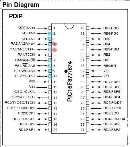
The following examples briefly explains how to setup ADC module when analog pins are dependent from each other, using PIC 16F877.
The following diagram is here to help knowing where analog pins (blue) are and where Vref pins (red) are:
Example 1: 16F877, with only one analog pin, no external voltage reference
-- beginning is about configuring the chip
-- this is the same for all examples for about 18F877
include 16f877
-- setup clock running @20MHz
pragma target OSC HS
pragma target clock 20_000_000
-- no watchdog, no LVP
pragma target WDT  disabled
pragma target LVP  enabled

-- We'll start to set all pins as digital
-- then, using ADC, we'll configure needed
-- ones as analog.
enable_digital_io()

include print
include delay
const serial_hw_baudrate = 115_200
include serial_hardware
serial_hw_init()

-- Step 1: ADC input pin setup we wil use channel 0
pin_AN0_direction = input
-- Step 2: Set A0 analog input and VDD as Vref
ADCON1_PCFG = 0b0000
-- Step 3: Use Frc as ADC clock
ADCON0_ADCS = 0b11
-- Now we can include the library
include adc
-- And initialize the whole with our parameters
adc_init()

-- will periodically send those chars
var word wmeasure
var byte bmeasure
const byte wprefix[] = "Result in high resolution: "
const byte bprefix[] = "Result in low  resolution: "

forever loop

   -- get ADC result, on channel 0
   -- this means we're currently reading on pin AN0 !

   -- access results in high resolution
   wmeasure = adc_read_high_res(0)
   -- wmeasure contains the result, as a word (byte*2)
   print_string(serial_hw_data,wprefix)
   print_word_dec(serial_hw_data,wmeasure)
   print_crlf(serial_hw_data)

   -- though we are in high resolution mode,
   -- we can still get a result as a byte, as though
   -- it were in low resolution.
   bmeasure = adc_read_low_res(0)
   print_string(serial_hw_data,bprefix)
   print_byte_dec(serial_hw_data,bmeasure)
   print_crlf(serial_hw_data)

   -- and sleep a little to prevent flooding serial...
   delay_1ms(200)

end loop
Example 2: 16F877, with 2 analog pins, 1 external voltage reference, that is, Vref+
This is almost the same as before, except we now want 2 (analog pins A0 and A1) + 1 (Vref+ A3), so yes we are using 3 analog pins here.
The beginning is the same, here's just the part about ADC configuration and readings. We use a for loop to go over the 2 analog pins A0 and A1:
-- Step 1: ADC input pin setup we wil use channel 0 and 1 (2 channels)
pin_AN0_direction = input
pin_AN1_direction = input
-- Step 2: Set A0 and A1 analog input and A3 as Vref
ADCON1_PCFG = 0b0011
-- Step 3: Use Frc as ADC clock
ADCON0_ADCS = 0b11
-- Now we can include the library
include adc
-- And initialize the whole with our parameters
adc_init()

-- will periodically send those chars
var word measure
var byte lowmeasure, channel
const byte prefix[] = "Channel "
const byte highstr[] = " (high) "
const byte lowstr[] = " (low) "
const byte suffix[] = ": "

forever loop

   -- loop over all channels and read
   for 2 using channel loop

  -- get ADC result, high resolution
  measure = adc_read_high_res(channel)
  -- send it back through serial
  print_string(serial_hw_data,prefix)
  print_string(serial_hw_data,highstr)
  print_byte_dec(serial_hw_data,channel)
  print_string(serial_hw_data,suffix)
  print_word_dec(serial_hw_data,measure)
  print_crlf(serial_hw_data)
  -- and sleep a little...
  delay_1ms(100)

  -- Even if we set high resolution, we can still access results
  -- in low resolution (the 2 LSb will be removed)
  lowmeasure = adc_read_low_res(channel)
  print_string(serial_hw_data,prefix)
  print_string(serial_hw_data,lowstr)
  print_byte_dec(serial_hw_data,channel)
  print_string(serial_hw_data,suffix)
  print_byte_dec(serial_hw_data,lowmeasure)
  print_crlf(serial_hw_data)
  -- and sleep a little...
  delay_1ms(100)

   end loop
end loop