I²C (Part 2) - Setting up and checking an I²C bus
In previous tutorial, we saw a basic overview of how to implement an i2c slave, using a finite state machine implementation. This time, we're going to get our hands a little dirty, and starts connecting our master/slave together.
Checking the hardware and the i2c bus...
First of all, i2c is quite hard to debug, especially if you don't own an oscilloscope (like me). So you have to be accurate and rigorous. That's why, in this second part of this tutorial, we're going to setup the hardware, and just make sure the i2c bus is properly operational.
Connecting two PIC together through i2c is quite easy from a hardware point of view. Just connect SDA and SCL together, and don't forget pull-ups resistors. There are many differents values for these resistors, depending on how long the bus is, or the speed you want to reach. Most people use 2.2K resistors, so let's do the same ! The following schematics is here to help:
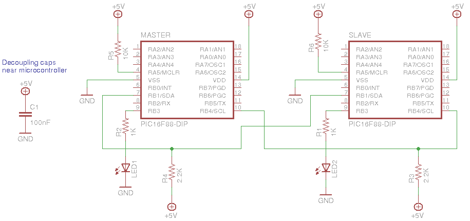
In this circuit, both PIC have a LED connected, which will help us understand what's going on. On a breadboard, this looks like that:
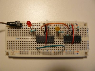
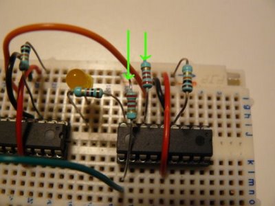
The master is on the right side, the slave on the left. I've put the two pull-ups resistors near the master:
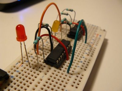
Green and orange wires connect the two PICs together through SDA and SCL lines:
The goal of this test is simple: check if the i2c bus is properly built and operational. How ? PIC 16F88 and its SSP peripheral is able to be configured so it triggers an interrupts when a Start or Stop signal is detected. Read this page (part of an nice article on i2c, from previous tutorial's recommendations).
- On power, master will blink a LED a little, just to inform you it's alive
- On the same time, slave is doing the same
- Once master has done blinking, it sends a i2c frame through the bus
- If the bus is properly built and configured, slave will infinitely blink its LED, at high speed
Note master will send its i2c frame to a specific address, which don't necessarily need to be the same as the slave one (and I recommand to use different addresses, just to make sure you understand what's going on).
- i2c_hw_slave.jal : main i2c library from the lib directory
- 16f88_i2c_sw_master_check_bus.jal: code for master from the sample directory
- 16f88_i2c_hw_slave_check_bus.jal : code for slave from the sample directory
The main part of the slave code is the way the initialization is done. A constant is declared, telling the library to enable Start/Stop interrupts.
const SLAVE_ADDRESS = 0x23 -- whatever, it's not important, and can be
                           -- different from the address the master wants
                           -- to talk to
-- with Start/Stop interrupts
const bit i2c_enable_start_stop_interrupts = true
-- this init automatically sets global/peripherals interrupts
i2c_hw_slave_init(SLAVE_ADDRESS)
And, of course, the Interrupt Service Routine (ISR):
procedure i2c_isr() is
   pragma interrupt
   if ! PIR1_SSPIF then
      return
   end if
   -- reset flag
   PIR1_SSPIF = false
   -- tmp store SSPSTAT
   var byte tmpstat
   tmpstat = SSPSTAT
   -- check start signals
   if (tmpstat == 0b_1000) then
      -- If we get there, this means this is an SSP/I2C interrupts
      -- and this means i2c bus is properly operational !!!
      while true loop
         led = on
         _usec_delay(100000)
         led = off
         _usec_delay(100000)
      end loop
   end if
end procedure
- check if interrupt is currently a SSP interrupts (I2C)
- reset the interrupt flag,
- analyze SSPSTAT to see if Start bit is detected
- if so, blinks 'til the end of time (or your battery)
Now, go compile both samples, and program two PICs with them. With a correct i2c bus setting, you should see the following:
http://www.youtube.com/watch?v=NalAkRhFP-s
On this next video, I've removed the pull-ups resistors, and it doesn't work anymore (slave doesn't high speed blink its LED).
http://www.youtube.com/watch?v=cNK_cCgWctY
Next time (and last time on this topic), we'll see how to implement the state machine using jallib, defining callback for each states.