PWM (Part 1) - Dimming a led with PWM
One PWM channel + one LED = fun
For now, and for this first part, we're going to see how to control the brightness of a LED. If simply connected to a pin, it will light at its max brightness, because the pin is "just" high (5V).
Now, if we connect this LED on a PWM pin, maybe we'll be able to control the brightness: as previously said, PWM can be used to produce variable voltages. If we provide half the value (2.5V), maybe the LED will be half its brightness (though I guess the relation between voltage and brightness is not linear...). Half the value of 5V. How to do this ? Simply configure the duty cycle to be 50% high, 50% low.
But we also said PWM is just about switching a pin on/off. That is, either the pin will be 0V, or 5V. So how will we be able to produce 2.5V ? Technically speaking, we won't be able to produce a real 2.5V, but if PWM frequency is high enough, then, on the average, and from the LED's context, it's as though the pin outputs 2.5V.
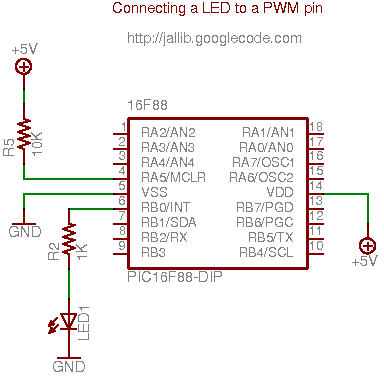
Building the circuit
Enough theory, let's get our hands dirty. Connecting a LED to a PWM pin on a 16f88 is quite easy. This PIC has quite a nice feature about PWM, it's possible to select which pin, between RB0 and RB3, will carry the PWM signals. Since I use tinybootloader to upload my programs, and since tiny's fuses are configured to select the RB0 pin, I'll keep using this one (if you wonder why tinybootloader interferes here, read this post).
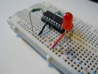
On a breadboard, this looks like this:
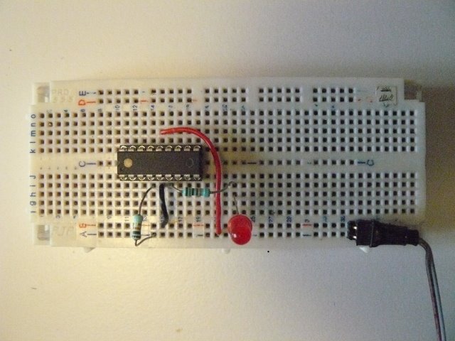
The connector brings +5V on the two bottom lines (+5V on line A, ground on line B).
 LED
is connected to RB0
LED
is connected to RB0
Writing the software
For this example, I took one of the 16f88's sample included in jallib distribution 16f88_pwm_led.jal, and just adapt it so it runs at 8MHz, using internal clock. It also select RB0 as the PWM pin.
So, step by step... First, as we said, we must select which pin will carry the PWM signals...
pragma target CCP1MUX RB0 -- ccp1 pin on B0and configure it as output
var volatile bit pin_ccp1_direction is pin_b0_direction
pin_ccp1_direction = output
-- (simply "pin_b0_direction = output" would do the trick too)
Then we include the PWM library.
include pwm_hardwareFew words here... This library is able to handle up to 10 PWM channels (PIC using CCP1, CCP2, CCP3, CCP4, ... CCP10 registers). Using conditional compilation, it automatically selects the appropriate underlying PWM libraries, for the selected target PIC.
Since 16f88 has only one PWM channel, it just includes "pwm_ccp1" library. If we'd used a 16f877, which has two PWM channels, it would include "pwm_ccp1" and "pwm_ccp2" libraries. What is important is it's transparent to users (you).
OK, let's continue. We now need to configure the resolution. What's the resolution ? Given a frequency, the number of values you can have for the duty cycle can vary (you could have, say, 100 different values at one frequency, and 255 at another frequency). Have a look at the datasheet for more.
What we want here is to have the max number of values we can for the duty cycle, so we can select the exact brightness we want. We also want to have the max frequency we can have (ie. no pre-scaler).
pwm_max_resolution(1)If you read the jalapi documentation for this, you'll see that the frequency will be 7.81kHz (we run at 8MHz).
PWM channels can be turned on/off independently, now we want to activate our channel:
pwm1_on()Before we dive into the forever loop, I forgot to mention PWM can be used in low or high resolution. On low resolution, duty cycles values range from 0 to 255 (8 bits). On high resolution, values range from 0 to 1024 (10 bits). In this example, we'll use low resolution PWM. For high resolution, you can have a look at the other sample, 16f88_pwm_led_highres.jal. As you'll see, there are very few differences.
Now let's dive into the loop...
forever loop
   var byte i
   i = 0
   -- loop up and down, to produce different duty cycle
   while i < 250 loop
      pwm1_set_dutycycle(i)
      _usec_delay(10000)
      i = i + 1
   end loop
   while i > 0 loop
      pwm1_set_dutycycle(i)
      _usec_delay(10000)
      i = i - 1
   end loop
   -- turning off, the LED lights at max.
   _usec_delay(500000)
   pwm1_off()
   _usec_delay(500000)
   pwm1_on()

end loop
Quite easy right ? There are two main waves: one
will light up the LED progressively (0 to 250), another will turn it off
progressively (250 to 0). On each value, we set the duty cycle with
pwm1_set_dutycycle(i) and wait a little so we, humans,
can see the result.
About the result, how does this look like ? See this video: http://www.youtube.com/watch?v=r9_TfEmUSf0
"I wanna try, where are the files ?"
To run this sample, you'll need latest jallib pack.