Serial Port and RS-232 for communication
In this tutorial we are going to learn how use TX & RX pins for serial communication to your PC, and also learn communicate with another PIC or external device via RS-232.
What is a serial port?
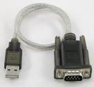
You may have forgotten about this important part of history "The serial port". You have forgotten because you have been too up-to-date on all the new technologies such as USB and Bluetooth, but you have left the good old technologies in the past. Well, now it's time to put that funny looking port on the back of your PC to some good use! If you don't have a serial port on your PC, you can get a USB to serial converter/adapter.
At one time, there was a wide range of devices that used the serial port such as a mouse, keyboard, old GPS, modems and other networking.
In our case, we will use a serial port to send data to our PC, or to send data a second PIC. I find it most useful for troubleshooting my code, and for sending other readable information to my PC without the use of additional hardware such as a LCD. LCDs & displays can be an expensive addition to your circuit.
What is RS-232?
RS-232 is the data transfer standard used on serial ports. Basically this is composed of one start bit, some data bits, parity bit, and one or two stop bits. The transfer speed as well as the number of start, stop and data bits must match for both the transmitter and receiver. We will not need to cover the way in which it is transferred since the PIC does it for us. We will only need to know the following:
1. The number of start bits (always 1)
2. The Parity (usually no parity)
3. The number of data bits (usually 8)
4. The number of stop bits (1 or 2)
5. The data transmission speed
6. The port number on your PC
You will be able to choose the transmission speed yourself. The Jallib library we will be using will use 1 start bit, 8 data bits, no parity, and 1 stop bit. Your other device, such as your PC will also need to know this information.
What do I need?
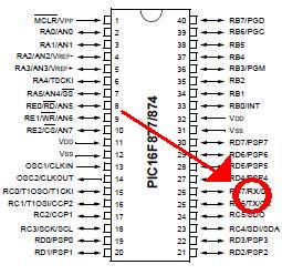
In the first part of this tutorial I will show you how to hook your serial port up to your PC. I will show you how to connect it to another PIC later on in this tutorial. I feel that connectivity to your PC is quite important. You will need:1. A PIC that has TX and RX Pin names. Most PIC's have them. Check your pinout diagram in the PIC's datasheet.
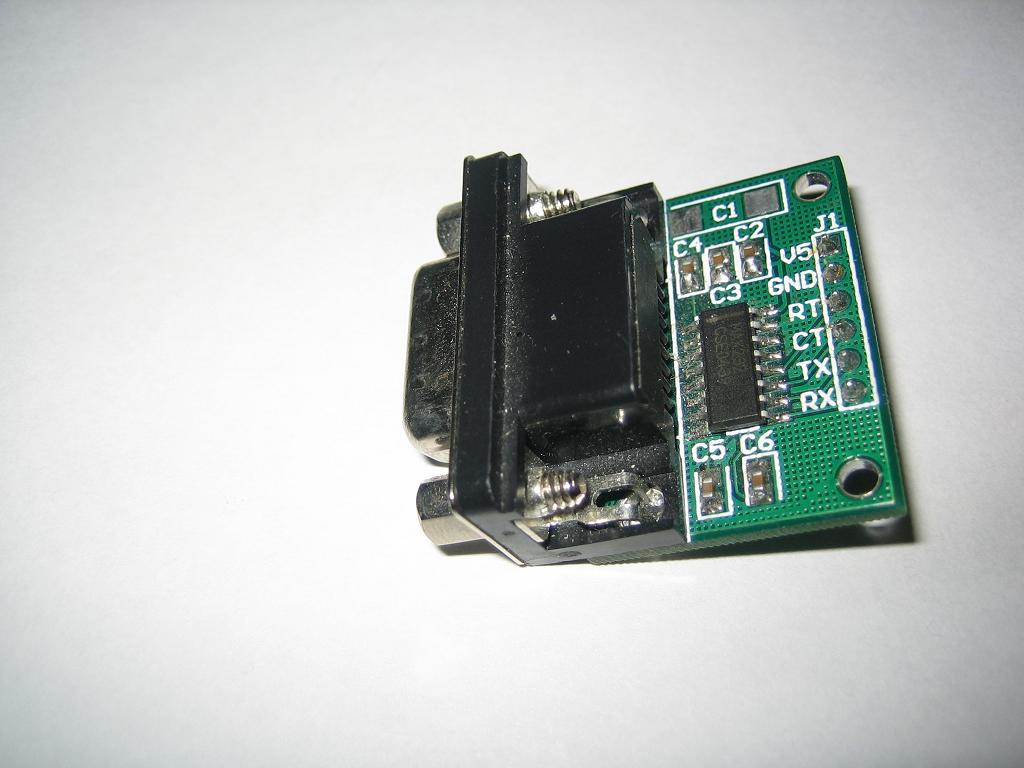
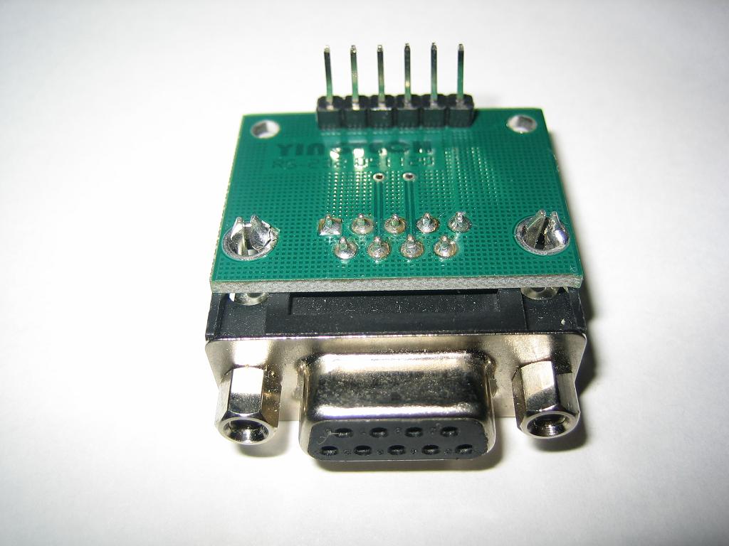
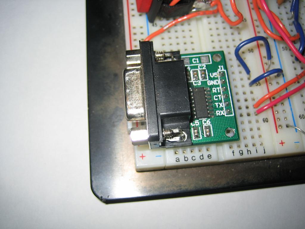
2. A serial port board. You can buy one on the net, or build your own. See Here for more information. A serial port board is needed for voltage conversion. Serial ports output voltages up to 12v and go lower than 0v.
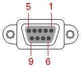
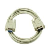
3. A regular RS-232 Cable (make sure it is not a null modem cable, they look the same). You can check what type of cable you have with your multimeter. Put your multimeter on each pin of your cable starting with pin 1. Check for a zero ohm reading. This will check that the pins are the same at both ends. Null modem cables have some pins crossed.
Build your circuit
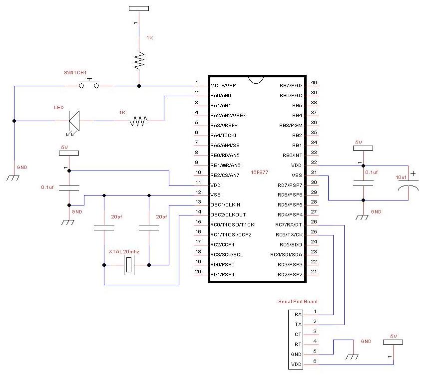
The circuit will be quite simple, you can take your blink a led circuit, and attach your serial port board. Here's a schematic with 16F877. We will be using the TX and RX pins:
Test your circuit
Before you write your own code, you should make sure your circuit actually works.
Go into the sample directory within your jalv2/jallib installation. Find your pic, and look for a serial hardware sample such as 16f877a_serial_hardware.jal. Then compile it and burn it to your PIC. Don't turn on your circuit yet, we are not ready.
On your PC, you will have to install some serial communications program such as RealTerm. RealTerm is free and open source. I will use RealTerm for this tutorial. You can download it here:
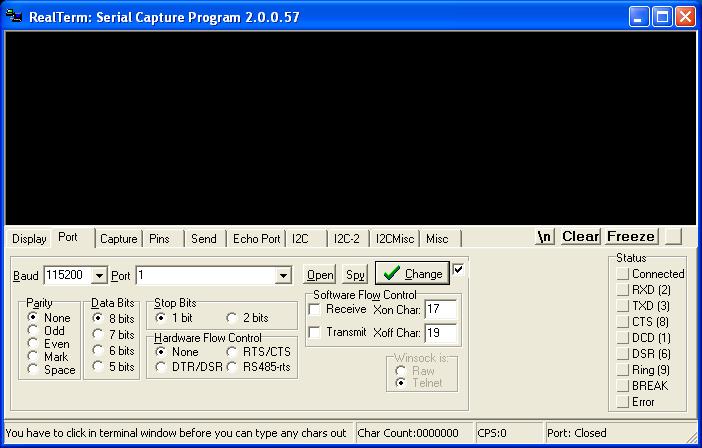
http://realterm.sourceforge.net/Open RealTerm and click on the "Port" tab, we need to select the port & speed, etc to the following values:
1. The Parity = no parity
2. The number of data bits = 8
3. The number of stop bits = 1
4. The data transmission speed = 115200
5. The port number on your PC
Now press "Open" in RealTerm and turn on your circuit. If you now see "Hello serial world......" showing in within RealTerm on your PC, you are able to receive data.
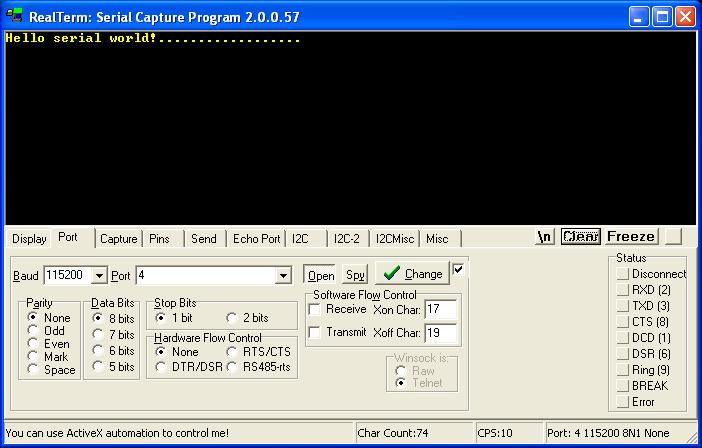
If your circuit doesn't work, your serial port board may have TX and RX switched (you can try switching your TX/RX wires around), or you may have selected the wrong port number, some PCs have more than one serial port.
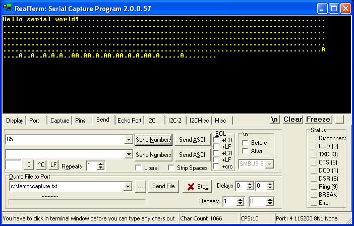
Now click on RealTerm's "send" tab, type in the number "65" in the first box and press "Send Numbers". If it sent ok, the PIC will echo this value back to you. You will see the ASCII character "A", which is the same as decimal 65. You can see a full ASCII chart at asciitable.com.
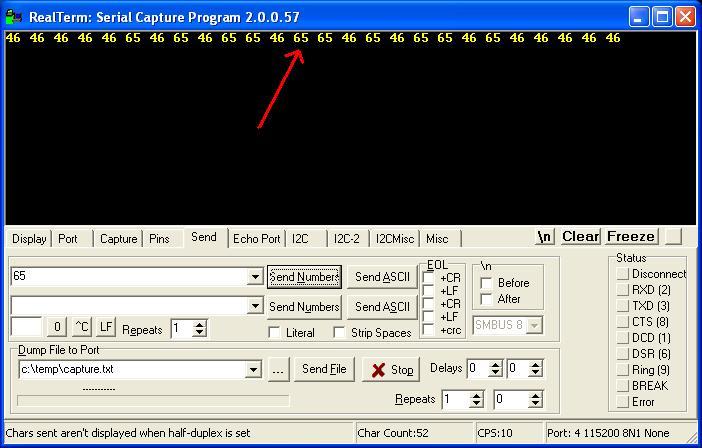
Now please change your RealTerm settings to receive decimal numbers by clicking on the "Display" tab, and choose "int8" under "Display As" at the left side. You will now continuously see the number "46" come in, and try sending the number "65" again. You will get the same number back on your screen.
int8 - shows integer numbers in RealTerm
Ascii - shows ascii text
Hex[space] - shows hex numbers with a space between each
Write code to send data from PIC to PC
Since this is one of the first circuits you will be building, I will try to give you detailed information so you can get some programming experience. We will continue with your code from "Blink a led". We will modify it to send data to your PC, Here's your original code:
include 16f877a                    -- target PICmicro
--
-- This program assumes a 20 MHz resonator or crystal
-- is connected to pins OSC1 and OSC2.
pragma target clock 20_000_000     -- oscillator frequency
-- configuration memory settings (fuses)
pragma target OSC  HS              -- HS crystal or resonator
pragma target WDT  disabled        -- no watchdog
pragma target LVP  disabled        -- no Low Voltage Programming
--
enable_digital_io()                -- disable analog I/O (if any)
--
-- You may want to change the selected pin:
alias   led      is pin_A0
pin_A0_direction =  output
--
forever loop
   led = on
   _usec_delay(250000)
   led = off
   _usec_delay(250000)
end loop
--
First we need to add serial functionality, I got the following code from 16f877a_serial_hardware.jal
-- ok, now setup serial;
const serial_hw_baudrate = 115_200
include serial_hardware
serial_hw_init()
So, now copy and past this into your code, I would put it somewhere after the line "enable_digital_io", and somewhere before your main program which starts at "forever loop".
This code will set your baudrate (speed), it will include the correct library file "serial_hardware", and it will initialize the library with "serial_hw_init()". You can change the speed if you wish, but you must change the speed in RealTerm as well.
Now we can put some code that will send data to your PC. If you want to send the number 65 to your PC, you must use this code:
serial_hw_data = 65This code works because it is a procedure/function within serial_hardware.jal, and you have already included the serial_hardware library. serial_haredware.jal can be found in the "lib" folder of your jallib installation. You can open that file and read notes within it for more information and for other usable variables, functions and procedures.
Let's make your code send the number 65 when the led turns on, and send the number 66 when your led turns off. Just place your code after your "led = on", and after "led = off"
forever loop
   led = on
   serial_hw_data = 65 -- send 65 via serial port
   _usec_delay(250000)
   led = off
   serial_hw_data = 66 -- send 66 via serial port
   _usec_delay(250000)
end loop
Or, if you wish to send Ascii letters to your PC instead, you could use the following:
forever loop
   led = on
   serial_hw_data = "A" -- send letter A via serial port
   _usec_delay(250000)
   led = off
   serial_hw_data = "B" -- send letter B via serial port
   _usec_delay(250000)
end loop
Both of the above loops will continuously send the decimal number's 65 and 66 via your serial port each time your led turns on or off. Your completed code should look like this:
include 16f877a                    -- target PICmicro
--
-- This program assumes a 20 MHz resonator or crystal
-- is connected to pins OSC1 and OSC2.
pragma target clock 20_000_000     -- oscillator frequency
-- configuration memory settings (fuses)
pragma target OSC  HS              -- HS crystal or resonator
pragma target WDT  disabled        -- no watchdog
pragma target LVP  disabled        -- no Low Voltage Programming

enable_digital_io()                -- disable analog I/O (if any)

-- ok, now setup serial;@jallib section serial
const serial_hw_baudrate = 115_200
include serial_hardware
serial_hw_init()

-- You may want to change the selected pin:
alias   led      is pin_A0
pin_A0_direction =  output

forever loop
   led = on
   serial_hw_data = 65 -- send 65 via serial port
   _usec_delay(250000)
   led = off
   serial_hw_data = 66 -- send 66 via serial port
   _usec_delay(250000)
end loop
Compile and burn your code to your PIC, then turn on your circuit. You should get this while your led is blinking:
Awesome, now that you can send data to your pc! This was an important step since it will greatly help you with your troubleshooting by sending you readable information such as text, numbers and other types of data.
If you feel your programming skills are not as good as they should be, practice practice practice! Continue using the language reference described in the document jalv2.pdf in the 'compiler' directory of your Jallib installation.
Write code to send data from PC to PIC
In the beginning, you may not have a use for sending data from your PC to your circuit, so you may skip this and go onto other things.
Here we are going to get the PIC to receive data from the PC. We will write some code that will only start blinking a led when you send data to the PIC. Also we will tell the PIC to send the number 65 to the PC once per second.
We will now learn to use the following variables from serial_hardware.jal:
serial_hw_data_available - If the PIC received data, this variable will equal TRUE, otherwise FALSE
serial_hw_data - If data is available, this variable will contain the data
So let's modify your current loop:
forever loop
   led = on
   serial_hw_data = 65 -- send 65 via serial port
   _usec_delay(250000)
   led = off
   serial_hw_data = 66 -- send 66 via serial port
   _usec_delay(250000)
end loop
First change it so it will send the number 65 to your PC every one second:
forever loop
   _usec_delay(1_000_000) -- one second delay
   serial_hw_data = 65    -- send 65 via serial port
end loop
We now can add an if statement to find out if there is serial data available:
forever loop
   _usec_delay(1_000_000) -- one second delay
   serial_hw_data = 65 -- send 65 via serial port

   if serial_hw_data_available then -- check if there is data available
   end if
end loop
You will need to create a variable "x" before your "forever loop", this variable will hold the data when you want to receive it:
var byte xNow you have a place to store the data, so you may now write a line within your "if" statement to get the data:
x = serial_hw_dataThen build a for loop after that to blink the led "x" number of times
for x loop   -- loop (x number of times) using data received on serial port
   led = on
   _usec_delay(250000)
   led = off
   _usec_delay(250000)
end loop
Here is your completed code:
include 16f877a                    -- target PICmicro
--
-- This program assumes a 20 MHz resonator or crystal
-- is connected to pins OSC1 and OSC2.
pragma target clock 20_000_000     -- oscillator frequency
-- configuration memory settings (fuses)
pragma target OSC  HS              -- HS crystal or resonator
pragma target WDT  disabled        -- no watchdog
pragma target LVP  disabled        -- no Low Voltage Programming

enable_digital_io()                -- disable analog I/O (if any)

-- ok, now setup serial;@jallib section serial
const serial_hw_baudrate = 115_200
include serial_hardware
serial_hw_init()

-- You may want to change the selected pin:
alias   led      is pin_A0
pin_A0_direction =  output

var byte x

forever loop              -- continue forever
   _usec_delay(1_000_000) -- one second delay
   serial_hw_data = 65    -- send 65 via serial port

   if serial_hw_data_available then -- check if data is ready for us
      x = serial_hw_data            -- get the data
      for x loop                    -- loop "x" number of times
         led = on                   -- turn the led on
         _usec_delay(250000)        -- 250ms delay
         led = off                  -- turn the led off
         _usec_delay(250000)        -- 250ms delay
      end loop                      -- loop
   end if                           -- end the if statement

end loop
As you can see, this code will do the following:
1. delay 1 second
2. send the number 65 via serial port
3. see if there is data waiting for us, if so, get it and blink the led (the number of times of the data received)
4. loop back to the start
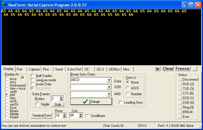
So, turn it on, you will start getting decimal numbers: "65 65 65 65 65" or ascii: "AAAAAA" in RealTerm. Now send your PIC the number 5, you will see your led blink 5 times. Now isn't that awesome!
PIC to PIC communication via serial port
Sending data to your PC is not the only use. If you have an extra PIC laying around, we can get two PIC's to talk to each other. And it's quite easy too!
I think you can do this on your own by now, you know how to make one PIC send data, and how to make a PIC receive data, so all you have to do is write some sending code on one PIC and receiving code on the other.
Build another circuit the same as your current one, then do the following:
1. connect the TX pin from PIC # 1 to the RX pin of PIC # 2
2. connect the RX pin from PIC # 1 to the TX pin of PIC # 2
On one of your PIC's, make it send data every one second, like we did before at Write code to send data from PIC to PC.
On the other PIC, make it loop continuously. Put an if statement in the loop that will see if there is data available, and if there is, make the led blink once, like we did at Write code to send data from PC to PIC.
You should then see your led blinking on your second PIC.
Wow, that was a lot, now I think you know your stuff!
Your Next Step
Now that you know how serial works, I suggest you take a look at the print and format libraries which will help you format numbers and strings in an easy & readable. Check out this tutorial:
Print & Format