USB (Part 2) - The PIC as a serial port
Using the Jallb USB library
In the previous section some introduction as given about what the Universal Serial Bus is about. In this section we will make use of the Jallib USB driver to create an application using the USB.
The Jallib USB library
Of course you can only use the Jallib USB library with PICs that have the USB hardware on board. This hardware is called the USB Serial Interface Engine (SIE). This SIE only supports the PIC to be a USB device, which means that it always needs a USB host like your computer. The host configures the PIC and initiates all USB transmissions.
- Using the PIC as a serial (COM) port
- Using the PIC as a keyboard
- Using the PIC as a mouse
- Using the PIC as a Human Interface Device (HID)
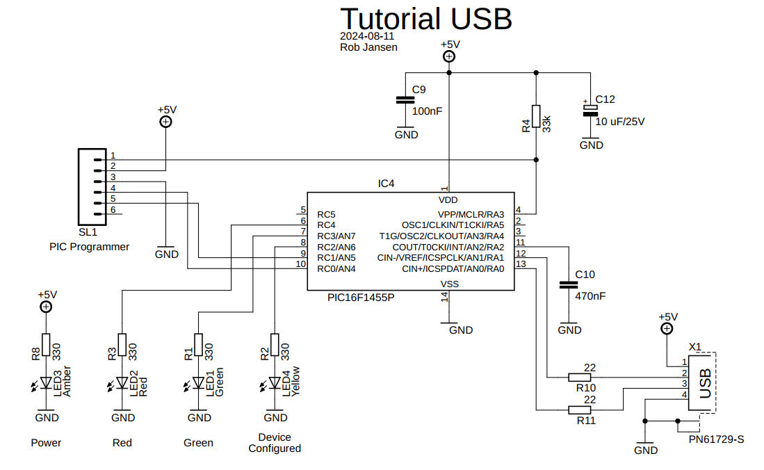
To show you how this works, we need some hardware and software. The hardware used for this Tutorial consists of a PIC16F1455 with some LEDs that can be controlled via USB. The schematic diagram of this hardware is given below.
In the following sample program the PIC will act as a serial port. From the computer (the host) we will control two LEDs connected to the PIC. The PIC will also send the status of the LEDs back to the computer. On the computer side, the terminal emulation program is used for sending the control commands to the PIC and for showing the message returned by the PIC.
The sample program explained
We start with the
configuration of the PIC. This is done via the setting the correct
pragma target and we set the target
clock. Note that for correct operation the USB hardware, the PIC
has to run at 48 MHz,
include 16f1455             -- Target processor.

pragma target clock         48_000_000

-- Settings for internal clock and system clock 48 MHz.
pragma target OSC           INTOSC_NOCLKOUT -- Internal clock
pragma target CLKOUTEN      DISABLED -- CLKOUT function is disabled.
pragma target PLLMULT       N3X      -- PLL Multipler Selection Bit, 3x

-- Other fuses.
pragma target CPUDIV        P1       -- NO CPU system divide
pragma target USBLSCLK      F48MHZ   -- System clock expects 48 MHz
pragma target PLLEN         ENABLED  -- 3x or 4x PLL Enabled
pragma target FCMEN         DISABLED -- Fail-Safe Clock Monitor is disabled
pragma target WRT           DISABLED -- Write protection off
pragma target STVR          ENABLED  -- Stack Overflow or Underflow will cause a Reset
pragma target LPBOR         DISABLED -- Low-Power BOR is disabled
pragma target IESO          DISABLED -- Internal/External Switchover Mode is disabled
pragma target PWRTE         DISABLED -- power up timer
pragma target BROWNOUT      DISABLED -- no brownout detection
pragma target WDT           DISABLED -- Watchdog disabled
pragma target MCLR          EXTERNAL -- External reset
pragma target LVP           ENABLED  -- allow low-voltage programming
pragma target VOLTAGE       MAXIMUM  -- brown out voltage
pragma target CP            DISABLED -- Program memory code protection is disabled

OSCCON = 0b1111_1100 -- Select PLL,3x, 16MHz internal oscillatoroutput the weak pull-up for that
pin is disabled. For this PIC only port A has the weak pull-up feature and
because of that we make port C output so that the pins are not
floating.-- Enable weak pull-up for port a and and set port c to output just to
-- have no floating input pins.
OPTION_REG_WPUEN = FALSE -- Enable weak pull-up for port a.
WPUA = 0b0011_1111 -- Weak-pull up for all inputs.
TRISC = 0b0000_0000 -- Port c output.-- Include serial library and print library for formatting print output.
include usb_serial
include print
-- Aliases for LEDs, active HIGH.
alias led_red is pin_C4
pin_C4_direction = output -- Pin 6 of 14 pin DIP.
alias led_green is pin_C3
pin_C3_direction = output -- Pin 7 of 14 pin DIP.
alias led_yellow is pin_C2
pin_C2_direction = output -- Pin 8 of 14 pin DIP.-- Variables.
var byte character
var bit red_value, green_value- Initialize the usb library
- Initialize (clear) all LEDs
- Report if the PIC USB device is configured (Yellow LED)
- Keep the USB going by frequently calling the function
usb_serial_flush()Note: The USB driver can also be used on an interrupt basis as described in the USB library and the USB sample programs. In that case theusb_serial_flush()is not required - Handle the commands sent by the computer and control the LEDs accordingly. A single character command will toggle the status of the LED from on to off or the other way around
- Return the status of the controlled LED to the computer after a command was received
- Return an error message if an incorrect command was received
-- ------------- The main program starts here  ------------------------

-- Setup the USB serial library.
usb_serial_init()

-- LEDs off.
led_yellow = FALSE
red_value = FALSE
green_value = FALSE

forever loop

   -- Update Red and Green LEDs.
   led_red = red_value
   led_green = green_value

   -- Poll the usb ISR function on a regular base,
   -- in order to serve the USB requests
   usb_serial_flush()

   -- Check if USB device has been configured by the host.
   if ( usb_cdc_line_status() !=  0x00 )  then
      led_yellow = TRUE
   else
      led_yellow = FALSE    -- disconnected
      red_value = FALSE     -- red led off
      green_value = FALSE   -- green led off
   end if

   -- Check for input character. If OK, toggle led value and report to host.
   if usb_serial_read(character) then
      if (character == "R") | (character == "r") then
         red_value = !red_value
         print_string(usb_serial_data, "Red LED is ")
         if red_value then
            print_string(usb_serial_data, "on")
         else
            print_string(usb_serial_data, "off")
         end if
      elsif (character == "G") | (character == "g") then
         green_value = !green_value
         print_string(usb_serial_data, "Green LED is ")
         if green_value then
            print_string(usb_serial_data, "on")
         else
            print_string(usb_serial_data, "off")
         end if
      else
         print_string(usb_serial_data, "Expecting 'r' or 'g'")
      end if
      print_crlf(usb_serial_data)
   end if

end loop
The complete program can be found in the sample
directory of the latest Jallib release under the name
16f1455_tutorial_usb_serial.jal.
- In order to initialize the PIC as USB device you have to enable RTS/CTS
- The USB serial baudrate and number of bits is not relevant
- Since we are using single character commands make sure to disable sending carriage return and/or linefeed after the character was entered, otherwise the PIC will return that as an unsupported command.