Memory with 23k256 sram
Learn how to use Microchip's cheap 256kbit (32KB) sram for temporary data storage
What is the 23k256 sram and why use it?
So, you need some data storage? Put your data on a 23k256!
If speed is your thing, this one is for you! This is FAST. According to Microchip's datasheet, data can be clocked in at 20mhz. The disadvantage to this memory however is that it will not hold it's memory when power is off since it is a type of RAM (Random Access memory).
If you wish to hold memory while power is off, you will have to go with EEPROM but it is much slower. EEPROM requires a 1ms delay between writes. In the time that I could write 1 byte to an EEPROM (1ms), I could write 2500 bytes to the 23k256 (if I can get my PIC to run fast enough).
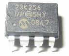
Yet another advantage, is that it is only 8 pins (as you can see from the image). Other RAM memories have 10 or so address lines + 8 data lines. If you haven't guessed yet, we are sending serial data for reads & writes. We will be using SPI (Serial Peripheral Interface Bus).
I suggest you start by reading the SPI Introduction within this book first.
You can read more about the 23k256 here:
What will I learn?
We will be using the jallib sram_23k256 library & sample written by myself. With this library, we will be able to do the following:
1. Initialization settings for 23k256.
2. Read settings from the 23k256.
3. Read & Write one byte to/from a specific address
4. Use the 23k256 as a large byte, word or dword array (32k bytes, 16k words, 8k dwords)
5. Fast read/write lots of data.
OK, lets get started
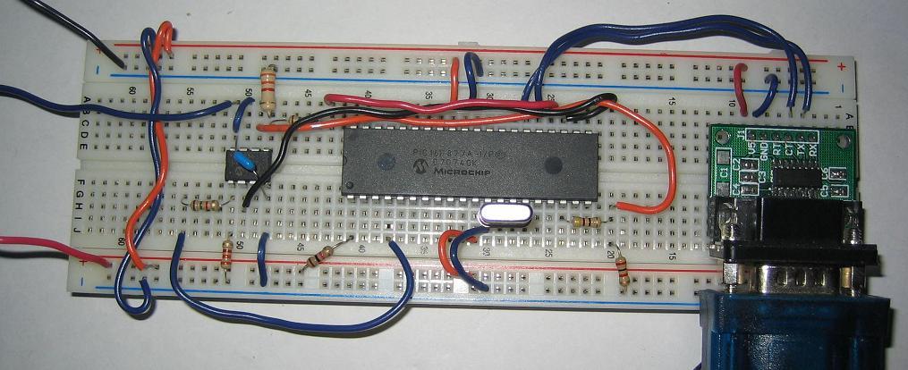
I suggest you start by compiling and writing the sample file to your PIC. We must make sure your circuit is working before we continue. As always, you will find the 23k256 sample file in the sample directory of your jallib installation "16f877_23k256.jal"
You will need to modify this sample file for your target PIC.
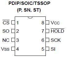
const bit SRAM_23K256_ALWAYS_SET_SPI_MODE = TRUEHere's the 23K256 pin-out diagram:
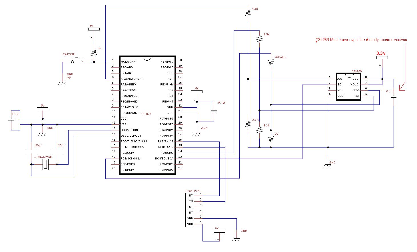
Now build this schematics. Notice the resistors for 5v to 3.3v conversion. Also notice that we are using the PIC's hardware SPI port pins. These pins are named (SDO, SDI, SCK) + One chip select pin of your choice.
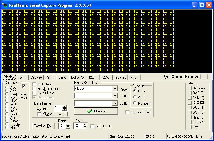
Plug in your serial port and turn it on (serial baud rate 38400). If it is working, you will get mostly the hex value "11" to your PC's serial port. Here's an image from my serial port software:
If it is not working, lets do some troubleshooting. First start by checking over your schematic. If your schematic is correct, the most likely problem is voltage levels. Check over your PIC's datasheet to see what the PIN types are, if any of the pins have CMOS level outputs, you will not need voltage conversion resistors.
In the past, I have had issues with the voltage conversion resistors on the SCK line.
Setup the devices
Since the beginning initialization has already been written for you, and you already know how to include your PIC, you can skip this section and go down to the 23k256 Usage section if you wish.
Take a look at the sample file you have. As you know, firstly, we will include your chip, disable all analog pins and setup serial communication.
include 16F877a                    -- target PICmicro
--
-- This program assumes a 20 MHz resonator or crystal
-- is connected to pins OSC1 and OSC2.
pragma target clock 20_000_000     -- oscillator frequency
-- configure fuses
pragma target OSC  HS              -- HS crystal or resonator
pragma target WDT  disabled        -- no watchdog
pragma target LVP  disabled        -- no Low Voltage Programming

enable_digital_io()                -- disable analog I/O (if any)

-- setup uart for communication
const serial_hw_baudrate  = 38400   -- set the baudrate
include serial_hardware
serial_hw_init()
As stated before, the 23k256 MUST be connected to the pic's SPI port, so let's setup the SPI port as well as the SPI library. We do not need to alias SPI hardware pins to another name. First include the library, then set the pin directions for the 2 data lines and the clock line:
-- setup spi
include spi_master_hw         -- includes the spi library
-- define spi inputs/outputs
pin_sdi_direction = input    -- spi input
pin_sdo_direction = output   -- spi output
pin_sck_direction = output   -- spi clock
Now that SPI data/clock pins are setup, the only pin left to define is the 23k256 chip select pin. If you have more then one device on the SPI bus, this chip select pin setup should be done at the beginning of your program instead. This chip select pin can be any digital output pin you choose to use.
-- setup chip select pin
ALIAS sram_23k256_chip_select             is pin_a2
ALIAS sram_23k256_chip_select_direction   is pin_a2_direction
-- initial settings
sram_23k256_chip_select_direction = output -- chip select/slave select pin
sram_23k256_chip_select = high             -- start chip slect high (chip disabled)
--
Choose SPI mode and rate. 23k256 uses SPI mode 1,1
We will start with peed SPI_RATE_FOSC_16. (oscillator/16). These are the speeds that are available:
SPI_RATE_FOSC_4 -- Fastest
SPI_RATE_FOSC_16 -- Mid speed
SPI_RATE_FOSC_64 -- Slower
SPI_RATE_TMR -- Use timer
spi_init(SPI_MODE_11,SPI_RATE_FOSC_16) -- init spi, choose mode and speedThis line tells the PIC to set the SPI mode before each read & write. If you have multiple devices on the SPI bus using different modes, you will need to set this to TRUE
const byte SRAM_23K256_ALWAYS_SET_SPI_MODE = TRUENow we can finally include the library file, and initialize the chip:
include sram_23k256 -- setup Microchip 23k256 sram
-- init 23k256 in sequential mode
sram_23k256_init(SRAM_23K256_SEQUENTIAL_MODE, SRAM_23K256_HOLD_DISABLE)
23k256 Usage
I'm going to go over this quickly since the code is simple.
Read & Write Byte
Write hex "AA" to address 1:
sram_23k256_write(1,0xAA) -- write byteNow read it back:
var byte data
sram_23k256_read(1, data) -- read byte
Byte Array
You can use the 23k256 as a large byte, word or dword array like this:
-- Example using 23k256 as a 32KByte array (at array address 2)
var byte data1
sram_23k256_byte[2] = 0xBB   -- set array byte 2 to value 0xBB
data1 = sram_23k256_byte[2]  -- read array byte 2, data2 should = 0xBB

-- Example using 23k256 as a 16K word array
var word data2
sram_23k256_word[3] = 0xEEFF     -- set array word 3 to value 0xEEFF
data2 = sram_23k256_word[3]      -- read array word 3, data2 should = 0xEEFF

-- Example using 23k256 as a 8K dword array
var dword data3
sram_23k256_dword[3] = 0xCCDDEEFF -- set array dword 3 to value 0xCCDDEEFF
data3 = sram_23k256_dword[3]      -- read array dword 3, data2 should = 0xCCDDEEFF
If you are looking for a quick way to write lots of data, you can use the start_write, do_write and stop_write procedures. You should not use any other SPI devices on the same SPI bus between start_write() and stop_write()
sram_23k256_start_write (word in address) -- sets the address to write to
sram_23k256_do_write (byte in data) -- send the data
sram_23k256_stop_write() -- stops the write process
Here's an example:
-- Example fast write lots of data
sram_23k256_start_write (10)
for 1024 loop
  sram_23k256_do_write (0x11)
end loop
sram_23k256_stop_write()
This works the same for the read procedures:
sram_23k256_start_read (word in address) -- sets the address to read from
sram_23k256_do_read (byte out data) -- get the data
sram_23k256_stop_read() -- stop the read process
-- Example fast read lots of data
sram_23k256_start_read (10)
for 1024 loop
  sram_23k256_do_read (data1)
  serial_hw_write (data1)
end loop
sram_23k256_stop_read()
Your done, enjoy!